DTT Project design
The Divertor Tokamak Test facility (DTT) is a new fusion device under construction in Frascati, Italy. DTT is a tokamak with 6 T on-axis maximum toroidal magnetic field carrying plasma current up to 5.5 MA in pulses with total duration up to 100 s. The D-shaped vacuum chamber is able to host a plasma with major radius R=2.19 m, minor radius a=0.70 m and average triangularity 0.3.
DTT is a divertor facility designed to accommodate a variety of divertor configurations, both in single and double null scenarios, in regimes where core and edge are in conditions of reactor-relevant power flow. In this context, DTT is designed to investigate high performance tokamak physics and to address core confinement to offer an integrated solution to this crucial aspect.
The auxiliary heating power coupled to the plasma at maximum performance is 45 MW, which allows matching ITER and DEMO PSEP/Rvalues, where PSEP is the power flowing through the last closed magnetic surface.

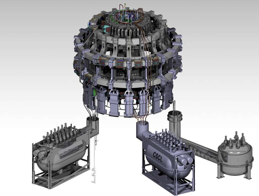
DTT superconducting system 3D model
DTT is a fully superconducting tokamak able to generate a magnetic field very close to those of ITER and DEMO. The three superconducting systems are the Toroidal (TF), the Poloidal (PF) Field and Central Solenoid (CS).
AUXILIARY HEATING POWER. The DTT auxiliary heating power coupled to the plasma at maximum performance will be 45 MW, shared between the three heating systems used in ITER and foreseen in DEMO: ion and electron cyclotron resonance heating and negative ion beams
(170 GHz ECRH, 60-90 MHz ICRH and 500 keV negative ion beam injectors).
The three systems will exploit the technologies developed for ITER and other relevant tokamak (as JT-60SA) with the aim to gain a high level of reliability. The heating systems will be installed in three subsequent phases of Tokamak operation to reach the maximum coupled power at the “Phase 3” of the Operational Programme.
MAGNETIC CONFIGURATIONS: DTT is being designed with a high level of flexibility. The reference configuration is the Single Null with Ip =5.5MA. Alternative configurations are allowed, including Double Null, Negative Triangularity.
DTT SUPERCONDTING MAGNET SYSTEM: In addition to the three superconducting systems (Toroidal, Poloidal Field and Central Solenoid) are included in the cryostats (4.5 K needed to operate the magnets) also the mechanical connections, the Feeders, distributing the current among the coils and the Current Leads,
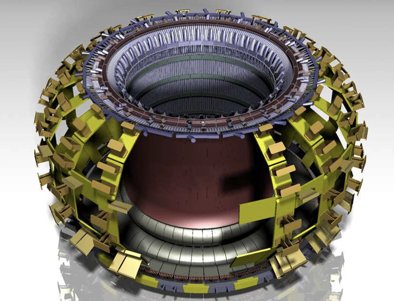
DTT VESSEL AND OUT OF VESSEL SYSTEM: The system is composed of several components for the containment of the plasma and of the superconducting magnets to be protected under vacuum by external heat sources. The design of Vacuum Vessel and in-vessel components is addressed mainly by the impacting phenomenon of disruption as prevailing loads.
Four sub-systems can be identified: (i) the vacuum vessel for plasma containment, with 82 ports connecting the inner vessel with the cryostat; (ii) the thermal shield and cryostat for the thermal shielding and vacuum containment of the superconducting magnets; (iii) the inner vessel components not directly exposed to plasma radiation, including the stabilization plates and three sets of in-vessel coils for fine plasma control and error field correction; (iv) the vacuum pumping, cleaning and fueling systems.
DTT IN-VESSEL PLASMA FACING SYSTEM
In-vessel plasma facing components constitutes the core of DTT facility. The device has been designed to be as flexible as required to test also divertor systems that are not yet conceived. For this reason, modularity and replaceability have guided its design.
The first wall is composed by several modules per sector (five per sector in the outboard, two for both inboard and top first wall).
Because of the specific mission of DTT, the divertor is the core of all the design activity. Within a strong cooperation with EUROfusion, the Divertor Design Review N. 1 has been successfully completed (and approved by EUROfusion).
Its configuration, constituted by 54 modules, 3 per sector, is compatible not only with the reference single null scenario with positive triangularity, like in ITER, but also with other alternative scenarios that might be considered as reference in DEMO.

In-vessel systems in the DTT 3D model
DIAGNOSTIC SYSTEM
A diagnostic equipment, characterized by suitable accuracy, reliability and space and time resolution, has been assessed to achieve the DTT scientific program.
A strategy for diagnostic implementation has been adopted to integrate on DTT a properly coverage of core, edge and divertor areas measurements, both to guarantee machine protection and plasma control and, in addition, to properly support DTT experiment mission and Research Plan. About 80 diagnostic techniques are planned in full power operation and 30% of these (about 25 systems) is the DAY0 equipment.
REMOTE HANDLING SYSTEM
A remote handling has been designed to carry out the preventive frequent maintenance actions scheduled several times during the lifetime of the facility. The system is designed to perform several functions including cut & welding, divertor modules handling, first wall lifting, diagnostic calibration, vessel inspections and so on.
The DTT project as it appears today is the result of a long effort that has developed over the years, from its conception to the engineering and construction phases of these times. Among the many publications documenting its development, we recall
- "Blue Book" (A. Pizzuto. Ed, “DTT Divertor Tokamak Test facility – Project Proposal Report. ”, 2019, ISBN 978-88-8286-318-0)
- "Green Book" (R. Martone, R. Albanese, F. Crisanti, P. Martin and A. Pizzuto. Eds, “DTT Divertor Tokamak Test facility – Interim Design Report”, 2019. ISBN 978-88-8286-378- 4


